How to Measure Stable Qualified Output During a Paper Cup Machine Acceptanc
Author:MINGYUAN Paper Cup Machine SuppliersFROM:Disposable Cup Machine ManufacturerTIME:2026-08-14
MENU
A paper cup machine acceptance test should not be judged by a brief peak-speed display. The useful result is stable qualified output: accepted cups produced under documented cup, paper, coating, mold, utility, inspection, and run conditions. This approach gives the buyer evidence that can be compared with the approved requirement instead of relying on a speed setting alone.
The acceptance plan should freeze the test inputs before the machine runs, follow cup formation from blank feeding to collection, separate accepted and rejected output, and record every interruption. If an input has not been agreed, the test can still provide observations, but it should not be treated as proof of an undefined production promise.
Define Stable Qualified Output Before the Test
Stable qualified output combines quantity, quality, time, and test conditions. Quantity alone cannot show whether the cups meet the agreed criteria. A displayed machine speed cannot show how many cups were accepted, how many were rejected, or whether the run included stops and manual intervention. The acceptance document should therefore define what counts as an accepted cup and how output, rejects, stops, and samples will be recorded.
Decision principle
Use the approved cup and material combination as the test unit. Record accepted output under that condition, and keep nominal or design speed as a separate reference rather than treating it as a production guarantee.
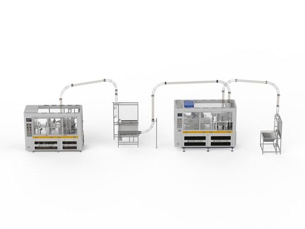
The buyer and supplier should also agree on the test boundary. A machine-only test is different from a test that includes inspection, rejection, counting, collection, sleeving, bagging, boxing, or another downstream handoff. If a downstream machine limits the flow, the record should identify the interaction instead of assigning every stop to the cup-forming machine.
Freeze the Cup and Material Conditions
The acceptance record should identify the finished cup by approved sample or drawing and list the material information actually supplied. Relevant details can include side-wall blank geometry, bottom stock, paper condition, coating type and side, print and die-cut condition, storage condition, and the mold or tooling installed for the test. Exact values belong in the record only when they come from approved documents or measured inputs.
PE-coated paper and water-based barrier materials should not be treated as automatically interchangeable. Their sealing behavior can depend on the approved material, surface condition, joining method, and machine configuration. If the project includes more than one coating condition, each supported condition needs its own evidence or a clearly documented limitation.
Verification note
Keep representative material and finished-cup samples from the agreed test where practical. Label them with the matching material batch, cup format, tooling condition, and test record so a later review is based on the same evidence.
Trace Quality Through the Forming Process
A useful acceptance inspection follows the production sequence. Side blanks should feed and separate consistently before the wall is formed and the side seam is established. Bottom stock should feed, punch or cut, transfer, and enter the joining position without creating unexplained variation. Heating and knurling conditions should support the approved material without relying on settings copied from another cup or coating.
Rim curling should be evaluated as a formed feature, not only as a final visual detail. Inspection and rejection should be observed to confirm that the supported defect logic behaves as documented. Counting and collection should maintain the agreed separation between accepted cups and rejected pieces, while the handoff to packing should not conceal jams or manual corrections.
Record Accepted Output, Rejects, and Interruptions
The log should make the result reproducible. Record the start and end of the agreed run, accepted quantity, reject quantity by the categories defined for the project, stops, restart events, material changes, setting changes, and manual intervention. A single total reject number may hide whether losses came from feeding, side sealing, bottom joining, rim curling, inspection settings, counting, or downstream handling.
Evidence area
What to document
Why it matters
Test condition
Cup identity, material and coating condition, tooling, utilities, inspection scope, and downstream boundary
Prevents results from being transferred to an untested configuration
Accepted output
Cups that meet the agreed criteria during the documented run
Separates qualified production from a speed display or gross count
Reject evidence
Defined defect categories, rejected pieces, and supported rejection behavior
Shows where losses occur and whether rejection protects accepted output
Interruptions
Stops, alarms, jams, adjustments, restarts, and manual intervention
Provides context for stability and future corrective work
Samples and sign-off
Retained samples, observations, open items, responsible parties, and approval status
Creates a traceable handover instead of a verbal conclusion
Evaluate Changeover and Mold Scope Separately
A stable run for one cup does not prove the complete size range. The project should identify which sizes are included, which mold and tooling sets are supplied, and which parts or settings change between formats. A change can involve guides, forming parts, bottom-cutting parts, heating positions, knurling components, rim-curling parts, counting settings, and another trial with the approved material.
If changeover is part of acceptance, define its starting condition, end condition, responsible operators, required parts, adjustment steps, safety controls, and the quality evidence required after restart. Keep changeover evidence separate from continuous-run output so neither result hides the other.
Verify Layout, Utilities, and Downstream Handoffs
Factory acceptance and site acceptance answer different questions. A factory test can show the configured equipment under the utilities and layout available at the test location. Site performance also depends on the installed electrical supply, voltage and frequency, grounding, compressed-air condition, material path, maintenance access, operator movement, finished-cup flow, and packing arrangement.
Site-readiness checks
Confirm the approved floor plan, working access, cleaning access, and safe maintenance space.
Confirm electrical and compressed-air conditions from approved machine documents rather than assumptions.
Map blank and bottom-stock movement, accepted-cup flow, reject removal, collection, and packing space.
Define interfaces with inspection, conveyors, counting, sleeving, bagging, boxing, or manual handling that are inside the project scope.
Record site differences that require adjustment or another verification run.
Close Acceptance With Records and Maintenance Handover
Acceptance should end with a controlled record, not only a signed statement that the machine ran. The record should identify the tested configuration, approved materials and cup, open items, agreed corrective actions, owners, evidence required for closure, and any limits on what the result demonstrates. Existing manuals, drawings, part lists, maintenance schedules, and training records should be checked against the delivered scope.
Maintenance handover matters because feeder condition, heating and knurling components, curling parts, guides, belts, bearings, sensors, pneumatics, inspection devices, and molds can affect repeatability. Operators should know routine cleaning and inspection boundaries, while work requiring qualified technicians or guarded access remains separated. A usable maintenance record helps the factory compare later performance with the accepted condition.
Frequently Asked Questions
Is the highest displayed speed the acceptance result?
No. The displayed setting can be recorded, but acceptance should focus on accepted cups under documented cup, material, tooling, utility, inspection, and run conditions, with rejects and interruptions recorded separately.
Can one paper or coating prove compatibility with every material?
No. A test supports the documented material condition. Another paper grade, coating type, coating side, blank condition, or storage condition may require separate confirmation and process verification.
Should every cup size be tested?
The tested sizes should follow the approved project scope and risk. At minimum, the record must clearly state which cup, mold, and tooling were tested and avoid extending that evidence to an untested format.
What happens when a downstream packing step causes a stop?
Record the event and identify the project boundary and handoff. This allows the buyer and supplier to distinguish cup-forming behavior from accumulation, counting, collection, or packing synchronization issues.
Conclusion
A meaningful paper cup machine acceptance test proves a defined production condition, not an undefined promise. Freeze the approved cup and material, trace the forming sequence, count only qualified output as accepted, document rejects and interruptions, and keep changeover, site utilities, downstream handoffs, and maintenance evidence visible.
Before the test, prepare one shared acceptance sheet that names the cup, material and coating condition, mold scope, test boundary, quality checks, records, and responsible parties. That document turns the run into evidence that can support commissioning and later production review.
Prepare the acceptance discussion with evidence.
Bring the finished-cup sample or drawing, side blank and bottom-stock information, coating condition, required size range, mold scope, output definition, factory layout, utility documents, packing plan, and proposed acceptance checks.



 Tel: +86-13362708280
 Email: george@paper-cupmakingmachine.com
 MP/WhatsApp: +86-13362708280
 Manufacturer Address:No.1588, Huaming Road, Feiyun Street,Ruian City Zhejiang Province -325200 China